This is an old revision of the document!
Table of Contents
Flarm Antenna
Introduction
The invention of FLARM was one of the most important innovations in gliding within the last decades. Today nearly all gliders are equipped with FLARM, which was primarily designed as an avionic anti collision system. But there are more benfits than the pure anti collision warning: many cross-country pilots use FLARM to see how other gliders climb. This functionality is often called “FLARM-radar”, which is supported by several flight computers and software. XCSoar also supports the FLARM-radar. If you are on cross country flight and you want to know how others climb in front of you, a good FLARM-antenna is the first choice. Unfortunately the often used toothpicker-antenna has a poor directivity. With a well designed, more directive antenna you can double your forward-looking range. If you are unsure about your glider's FLARM-performance, you can test your actual range here: FLARM range analyzer. You need an igc-file, downloaded from your FLARM, to see if your range is acceptable. If not, time to build a new FLARM antenna…
Antenna Description
The proposed antenna type was invented around 1950 by the swiss radio amateur Rudolf Baumgartner, who had the callsign “HB9CV”, which later served for the naming of the antenna. Wikipedia-Article in German.
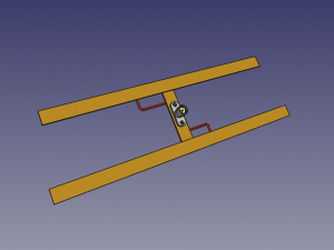
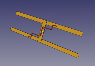
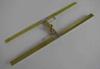
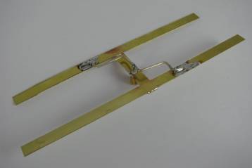
Views of the HB9CV, on the left side the coaxial SMA-flange connector, on the right some feeding details. The z-shaped wire is used to transform the antenna impedance to the commonly used 50 Ω-system (impedance matching) and to provide the correct phase relationship to each radiating element, thus serving as a kind of inherent balun. This feeding principle is also known as “gamma-match”.
The HB9CV-Antenna has several benefits:
- Good Directivity
- Good Impedance Matching
- Moderate Gain
- Simple Structure
- Acceptable Dimensions (approx. 17 x 5 cm)
- Optimum Performance with minimal effort
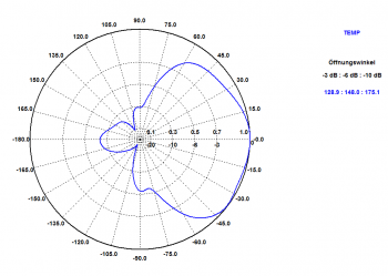
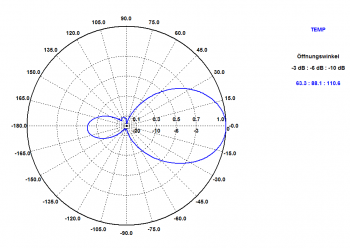
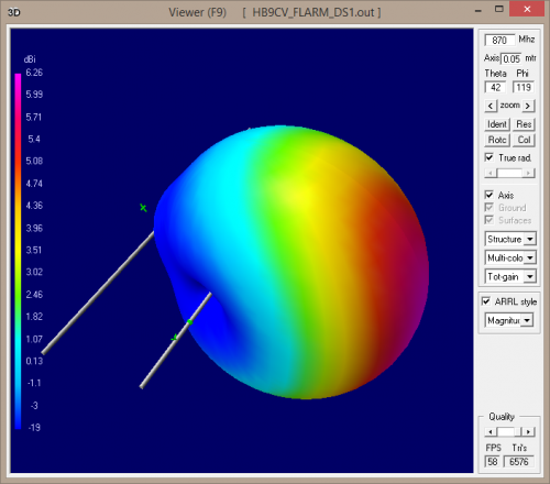
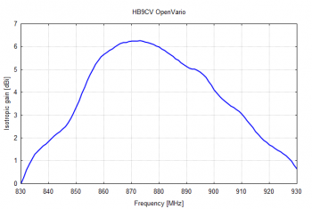
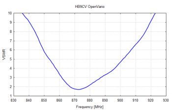
The HB9CV has been adapted to the FLARM-Frequency range of 868 MHz, where the wavelength λ = 34.6 cm. The performance was proven by measurements on a professional antenna test site using vector network analyzers, numerical simulation was done with NEC and last but not least tested in some glider installations.
Antenna Pattern and Gain
Required Parts
The material costs for the antenna are typically between 10 and 20 Euro.
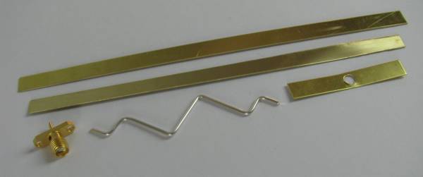
- Some solderable sheets of metal (brass, copper), total length approx. 370 x 8 mm, thickness: 0.5 … 1 mm
- copper wire diameter approx. 1…1.5 mm (strip a cable)
- SMA female flange connector
- Styrodur or comparable hard foam material
- Coaxial Cable 0.5 m to 1 m length with two SMA-male connectors
- Self adhesive tape
Building the Antenna
The build process of the antenna is very simple if you are familar with soldering. If you have all parts at hand, you can manage it within one or two hours. The design has been well proven by a professional antenna designer and can be regarded as absolutely reproducible and reliable, even in a DIY-environment. Here are two templates scaled 1:1 to be printed on a piece of paper, which can be used to simplify the build process. The first one includes the flat metal strips, the second one includes the bending of the feed wire.
Printable Soldering Template1 MB
Printable Feed-Wire Bending Template 0.4 MB
- Place the three metal strips on the paper-template and solder them together with a strong iron.
- Bent the copper wire according to the template.
- Solder the SMA-flange connector to the antenna structure.
- Adjust the gamma-match copper wire to an average spacing of approx 5 mm to the flat metal strips.
- Solder the copper wire to the antenna structure and the inner conductor of the SMA connector.
- Prepare the coaxial cable with the SMA-connectors.
- Cut the two Styrodur-plates to the desired dimensions and embed the antenna.
- Close the sandwich and secure it with self adhesive tape.
You are done…
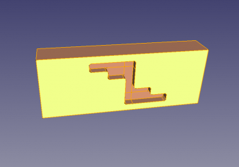
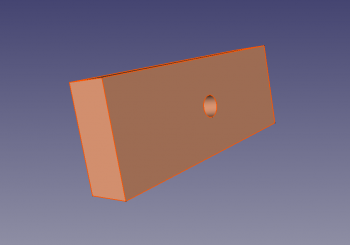
Here are some examples how to cut the Styrofoam Blocks to embed the Antenna. The outer dimensions are approx. 30 x 185 x 70 mm for each block. The z-shaped cutout is for the bent wire, the circular hole for the coaxial cable. You can connect the halves with self-adhesive tape or tiewraps alternatively.
Placement in the Glider
Placing the antenna in the glider is a real challenge because of several restrictions. Reflecting obstacles in your fuselage or cockpit will influence the antenna pattern significantly, the closer they are, the worser. Even a very good antenna may be useless if not installed in a proper way, therefore try to comply with the following rules for antenna placement:
- Keep antenna away from metallic structures and carbon fibre
- Vertical Polarisation is mandatory
- Do not bent the coaxial cable around corners
- Keep your visual area free
- The shorter element must point in forward direction
- Use Styrodur or comparable material for fixing the antenna in the fuselage
- Test your installation with the FLARM range analyzer tool
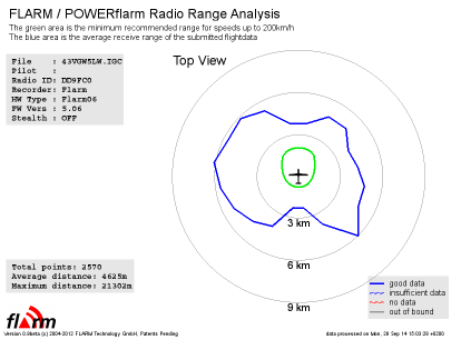 FLARM range analyzer result of a real life installation. The data is obtained using statistical methods. The more points measured, the better the quality of the data. The recommendation is to have a flight duration of 30 min at least and FLARM contact to at least 5 different gliders. At the moment there is only horizontal pattern data (top view) available, but vertical data would be very interesting as well. The picture shows the actual range with the blue trace and the minimum recommended requirement with a green trace. If both traces intersect, there is much room for improvement… For readers being interested in detailed information about FLARM, have a look at this: http://flarm.com/wp-content/uploads/2015/08/FLARM-System-Design-and-Compatibility.pdf
TODO: add fotos of installations
