Table of Contents
DC-DC-Converter Board
Description
The Step-Down Voltage Regulator Board (sometimes also referred as DC-DC-converter or buck-converter) is the main power supply of the Openvario. The LM 2596 step down voltage regulator is the major component of the small PCB, which is responsible to provide stable 5 V DC voltage supply for the cubieboard. This small PCB can be obtained via ebay from various vendors for little money. The input voltage may vary typically between 8 V and 20 V DC, the output-voltage can be adjusted to 5 V using the spindle-potentiometer and a digital multimeter connected to the output. A typical load condition is 12 V input voltage and 500 mA input current, which corresponds to a power of 6 W. The efficiency of the step down regulator is rated with at least 73% in the datasheet, resulting in 4.38 Watt output power at 5 V and 0.88 A. With my DC-DC-converter the measured efficiency was 80% with 12 V input, 5 V output and a 5 Ohm load.
Testing
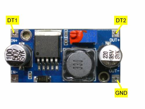
Test and adjust the small PCB seperately before connecting it to the other PCBs! Connect GND and DT1 to an adjustable 12 V DC power supply. Connect a Multimeter to GND and DT2 and select the 20 V DC-range or comparable. After the output voltage has been adjusted to 5V, it is recommended to seal the spindle potentiometer with screw securing color or glue against unintentional changes. Check the temperature of all components with your finger under load conditions for 15 minutes. All components should not heat up excessively. Connect a multimeter to the output-terminals and a laboratory power supply with adjustable output voltage to the input terminals. Vary the input voltage at DT1 from 8 V to approx. 15 V and watch the output voltage at DT2, which should be stable within 4.9 V to 5.1 V. After a successful voltage adjustment and temperature control the PCB can be soldered to the Adapterboard with 4 bent wires.
Step Down Regulator Board (Top View)
Test Points DC-DC-Converter
| Test Point | Description | Nominal Value | Measured | Remarks |
|---|---|---|---|---|
| DT1 | 12 V DC IN | 12 V | Change the Voltage from 8 V to 15 V and watch DT2 to be constant | |
| DT2 | 5 V DC OUT | 5 V | Main Power Supply for all Openvario-Boards, connected to CB1, noise ripple test is optional | |
| GND | GROUND | 0 V | Ground for all Openvario-Boards including Cubieboard |
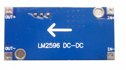
Step Down Regulator Board (Bottom View)
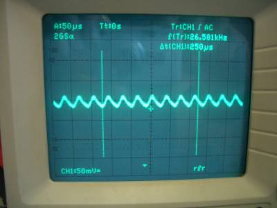
Noise Ripple Test on 5 V DC
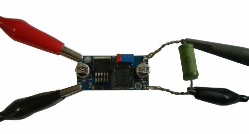
Testing is made under load conditions with an oscilloscope (optional). A resistor of 5 Ohm is used as dummy load. An oscilloscope is connected to the load resistor to see the noise ripple on the DC-voltage, caused by the PWM inside the buck converter. A residual noise ripple of 25 mV on the 5 V DC is typical.
Links to Datasheets
http://www.ti.com/lit/ds/symlink/lm2596.pdf
Continue testing the Adapterboard
Check the Connections with the Cubieboard
Back to Electrical Tests


