Openvario
Cubieboard
The Cubieboard does not require special testing under normal circumstances. But there are some cable connections to be made which are required for a reliable function of your Openvario.
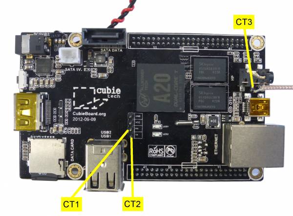
Cubieboard 2A20 (top view)
Test Points Cubieboard (Connected to Adapterboard via 2 "Cubieconnects")
| Test Point | Description | Nominal Value | Measured | Remarks |
|---|---|---|---|---|
| CT1 | CUBIE RX | LOGIC 3.3 V | Required for Debugging, connected to AT8, accessible from outside near RB4 | |
| CT2 | CUBIE TX | LOGIC 3.3 V | Required for Debugging, connected to AT8, accessible from outside near RB4 | |
| CT3 | CUBIE HP | TRIANGULAR | Headphone Output for Audio-Vario, connected to Sensorboard ST6. Volume Control is made using alsamixer |
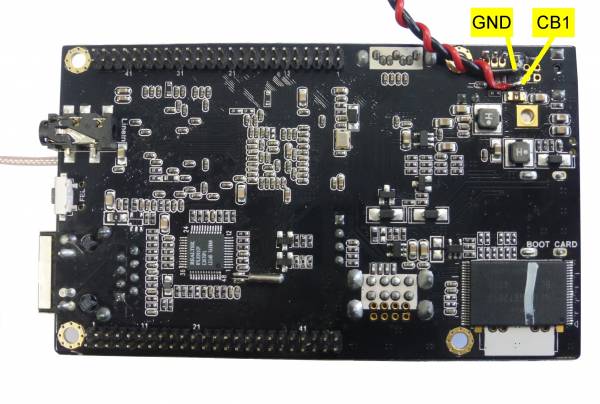
Cubieboard 2A20 (bottom view) with twisted power supply cable ↔ DC-DC-converter output.
| Test Point | Description | Nominal Value | Measured | Remarks |
|---|---|---|---|---|
| CB1 | CUBIE 5V | 5 V DC | Main Power Supply from DC-DC-Converter DT2 | |
| GND | CUBIE GND | 0 V | Ground, connected to DC-DC-Converter GND |
Continue testing the Adapterboard
Continue testing the RJ45-Board
Continue testing the Sensorboard
Back to DC-DC-Converter
Back to Electrical Tests
Back to OpenVario Hardware Architecture


