Table of Contents
RJ45-Board
Description
The RJ45-Board is very simple, it comes with 4 self-resetting polyfuses, 4 RJ45-female connectors in one shielded housing and a 12-pin connector. Therefore the probability for mistakes is very low. Verify the correct orientation of the ribbon cable between Adapterboard and RJ45-Board.
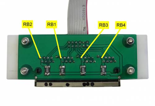
RJ45-Board with Test Points
Test Points RJ45-Board (connected via 12-pin ribbon cable to Adapterboard with Display and Cubieboard)
| Test Point | Description | Nominal Value | Measured | Remarks |
|---|---|---|---|---|
| RB1 | 12 V IGC T1 | 12 V | If not present, check orientation of 12-pin connector | |
| RB2 | 12 V IGC T2 | 12 V | If not present, check orientation of 12-pin connector | |
| RB3 | 12 V IGC T3 | 12 V | If not present, check orientation of 12-pin connector | |
| RB4 | 12 V IGC DBG | 12 V | Debug-Terminal, only required for Developers, if you want to know what is inside, check this out: serial_console_boot_log. The signal comes from CT1 and CT2, goes via AT8, is level shifted and ends near to RB4 |
Connectivity to external NMEA-equipment (Flarm, Logger, ...)
The Openvario has rich choices to connect external equipment with RJ-45 connectors in IGC-pin layout. Nearly all loggers, Flarms, Varios from the world of gliding come with the dedicated IGC-Layout, which has become a “Quasi-Standard” within the years.
Caution: Do not connect the Nano-Logger directly because of incompatible Pin-Assignment! The Nano-Logger needs a specialized cable to be connected! Before connecting any external NMEA-device via a RJ45-patch cable, be sure about the correct Pin-Assignment.
RJ45-IGC Pin Assignment
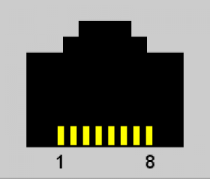
RJ45 IGC-Layout (view into female connector)
| RJ 45 Pin | Description | Remarks |
|---|---|---|
| 1 | +12 V | Supply for external device, fused |
| 2 | +12 V | Supply for external device, fused |
| 3 | NC | Not connected |
| 4 | NC | Not connected |
| 5 | RX | RX from logger / device |
| 6 | TX | TX to logger / device |
| 7 | GND | Ground |
| 8 | GND | Ground |
Settings in XCSoar
- required Information: Baud Rate, Device Driver Name, Port Name
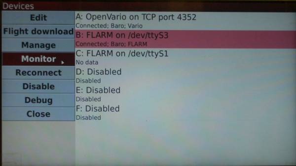
- xcsoar Device Manager (Config → Device)
- Monitor the NMEA output of your Device, if output is nonsense, try another Baudrate
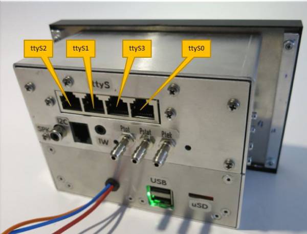
RJ45 Port Names
XCSoar Device Manager
All Details about XCSoar can be found in the Manual: http://www.xcsoar.org/discover/manual.html
Go back to testing the Adapterboard
Go back to the Cubieboard
Continue testing the Sensorboard
Back to Electrical Tests
Go to Setup Guide


