Table of Contents
Adapterboard
Description
The Adapterboard carries a small island PCB, which comes with the LM2596 step down voltage regulator. This board is called DC-DC-Converter and shall be tested and adjusted before soldering on the Adapterboard.
The Adapterboard (sometimes also referred as Mainboard) comes mainly with two MAX 3232 UART and the 30-pin LVDS FPC Display connector. It serves as main interface to the Cubieboard with its 96-pin GPIO. The 96 GPIO-pins of the Cubieboard are split into two seperate connectors with 2×24 pins each, which is called “Cubieconnect”. The corresponding two connectors on the Adapterboard come by default with 2×25 pins (this is not a bug, it is a matter of availability). Therefore it is important to align the connectors at the correct side or alternatively, cut the 2×25 into a 2×24 connector with a saw. The other components are usually not very critical. The Schottky diode must be checked for the correct polarity, as well as the 3.3 V voltage regulator TS2940. The are some photos out there showing the wrong orientation of the 3.3 V regulator, be careful and verify it before energizing. Further there is an Analog to Digital Converter ADS1110 (ADS1100 is also possible) on the Adapterboard, which is responsible for the battery voltage indication. The nominal Battery Voltage of 12 V is divided by R1 and R2 into 0.92 V and measured by the ADS1110, which is connected to the i2c-Bus, its address is 0x48. Tests can be made using i2cdetect. The scaling of the AD-Converters (ADS1100 uses the 3.3 V as external reference, whereas ADS1110 comes with a built-in reference of 2.048 V) is made in the file /opt/conf/sensord.conf. Some Builders decide to use a Touchscreen as input device, others prefer a Remote Stick or Rotary Encoders and Pushbottons.
Test Points Adapterboard (without Display, Cubieboard and Sensorboard)
| Test Point | Description | Nominal Value | Measured | Remarks |
|---|---|---|---|---|
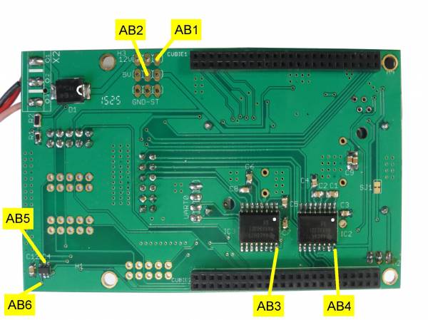
| AB1 | 12 V DC D1 | 12 V | If not present, check polarity of Diode D1 | |
| AB2 | 5 V DC D1 | 5 V | If not present, check connection to DC-DC-converter | |
| AB3 | MAX 3232 VCC IC2 | 3.3 V | VCC at Pin 16, if not present, check orientation of MAX3232 IC2 and AT3 | |
| AB4 | MAX 3232 VCC IC3 | 3.3 V | VCC at Pin 16, if not present, check orientation of MAX3232 IC3 and AT3 | |
| AB5 | AD1110 VDD IC4 | 3.3 V | VDD at IC4 Pin 5, I2C Address 0x48, I2C-Testing can be made later together with Sensorboard | |
| AB6 | AD1110 Vin+ IC4 | 0.92 V | Vin+ at IC4 Pin 1, Voltage Divider R1=10kOhm and R2=120kOhm |
Adapterboard Bottom with Test Points
| Test Point | Description | Nominal Value | Measured | Remarks |
|---|---|---|---|---|
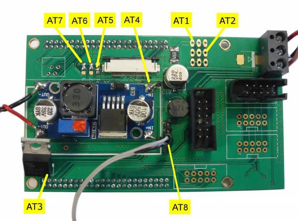
| AT1 | 12 V DC | 12 V | If not present, check D1 (bottom) for correct polarity, do not place D2! | |
| AT2 | 5 V DC IN | 5 V | Main Power Supply for the Cubieboard | |
| AT3 | 3.3 V DC IC1 | 3.3 V | If not present, check orientation of regulator IC1. Output is Pin 3, Input is Pin 1 (5V) | |
| AT4 | DISP VCC | 3.3 V | Display Connector Pins 2,3. Be sure that no other boards are connected. Risk of short circuit! |
Adapterboard Top with Test Points
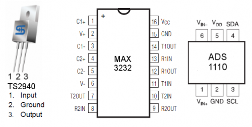
Pin Assignment of the parts used
Links to Datasheets
TS2940 Voltage Regulator 3.3 V
ADS1110 Analog to Digital Converter
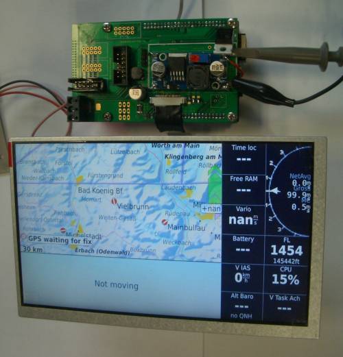
If all previous tests have been successful, it is time to combine the Adapterboard with the Cubieboard (via 2 x 48 pin GPIO connectors and a soldered twisted power supply cable from DC-DC-converter output to Cubie 5V input) and the FPC-cable between Adapterboard and Display. Prepare a MicroSD-card with a recent Openvario-Image suitable for your display variant and put it into the microSD-slot. Switch the power on and your Openvario should now boot for the first time! The typical boot time required is around 30 seconds to a minute. Watch the screen, two TUXes should appear after 15 sec.
Test Points Adapterboard (with Display and Cubieboard connected but without Sensorboard)
| Test Point | Description | Nominal Value | Measured | Remarks |
|---|---|---|---|---|
| AT5 | DISP JMP VM | Visual Check | If Display flickers or is mirrored (vertical), check solder jumpers | |
| AT6 | DISP JMP HM | Visual Check | If Display flickers or is mirrored (horizontal), check solder jumpers | |
| AT7 | DISP JMP PWM | Visual Check | If Display Background Illumination is dark, check solder jumpers | |
| AT8 | UART CUBIE | Visual Check | UART-cable from Cubieboard CT1, CT2, Rotate if Openvario does not boot |
The OpenVario is alive! Congratulations…
Check cables connected to the Cubieboard
Continue testing the RJ45-Board
Continue testing the Sensorboard
Back to Electrical Tests
Back to OpenVario Hardware Architecture


